I spent quite a bit of time this weekend working on the car. I’d guess six or seven hours spread between yesterday and today. I would’ve liked to have done more and would’ve liked to have had one weekend of work where I didn’t get hung up because I couldn’t find parts I needed, but I still got some work done on both the fuel lines and more wiring.
Yesterday was focused on wiring. I had intended to get as much of the wiring done as I could that touched the switches on the dash. I’ve got one bit of screwy wiring after another on this car, so I knew I was going to basically have to redo all of the dash wiring that came with the Ron Francis harness. I’ve said it before, and I’ll repeat it again: buying this harness was a mistake. I can’t recommend against it strongly enough for people who are building one of these cars if you’re doing anything out of the ordinary. Half the wiring isn’t needed if you’ve got EFI, and the other half is just wrong if you’re doing anything else unusual. C’est la vie.
The headlights I’m using are the Osram Xenarc HID lights I’d used for years in my 911. These are great HID lights, with a very nice light pattern and really are great for night driving. The wiring harness for them has one 20 amp circuit per light. The lights really only draw about 3 amps when running (each), which is a lot less than a normal halogen bulb, but the first second when they are firing they can draw quite a bit of power. (I think its closer to 12 amps, but 20 gives a safer overhead, I suppose…)
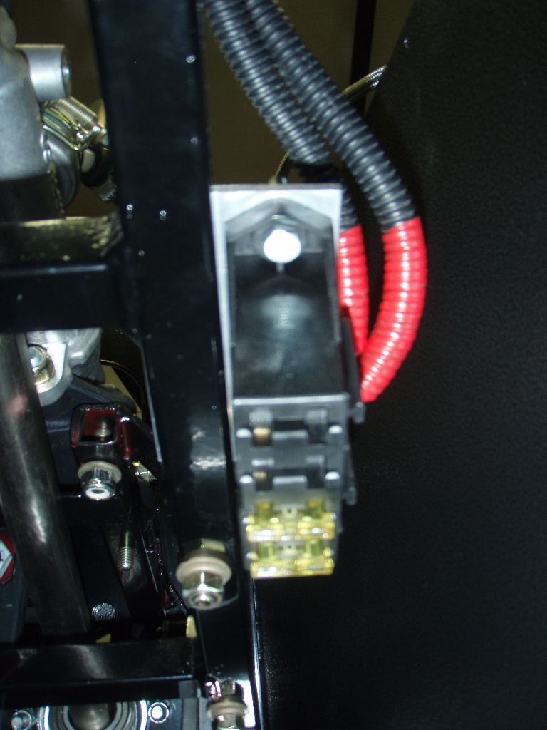
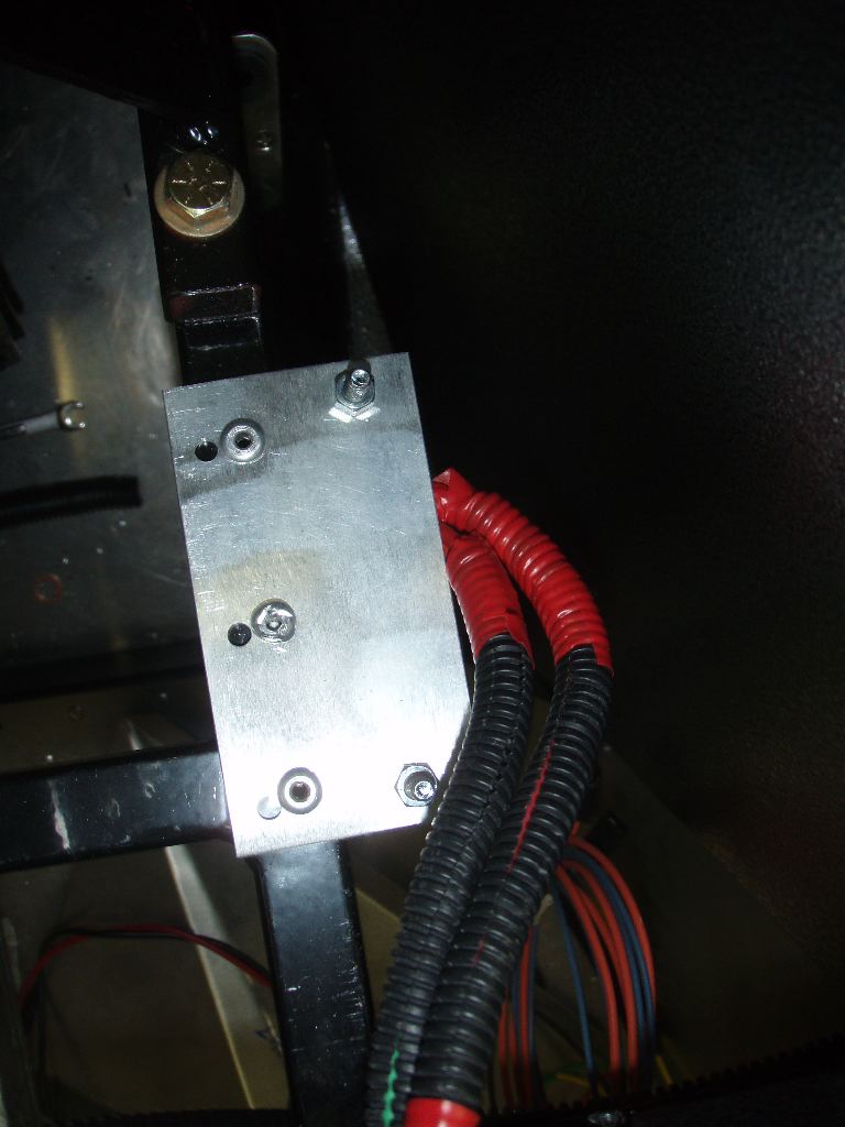
Having the inline fuses would’ve made replacing them very difficult if they ever blew (which is unlikely, but the mere thought would’ve jinxed me…). A week or two ago I ran the original alternator feed from the Ron Francis harness to a 4-position fuse panel. This is one of the reasons I did that. I used two of the positions for the left and right HID power feed.
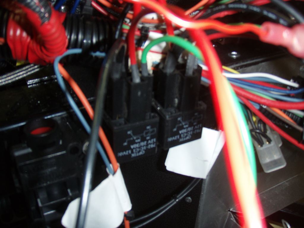
The power basically runs from the fuses into two relays behind the dash. The headlight switch controls each of these relays and feeds power through the harness I’d built a few months ago up to the HID ballasts on the front X-member. (Yes, the wiring behind the dash is turning into a giant festering mess… I’m not happy with it, but there’s a lot of stuff crammed into a very small space.)
In the post about the creation of the new front chassis harness with the power feeds to the ballasts, I had mentioned that I left the stock headlight wiring. I’d done this in case I ever had issues with the HID lights, as these are discontinued and spare parts may be very hard to come by pretty soon. As part of wiring the headlight power, I needed to figure out how to best connect things together so I wouldn’t have to rewire everything behind the dash (or on the dash) if I needed to switch. Basically, I wanted both circuits to be powered.
I screwed this up — miswired a bunch of things, but thankfully I noticed I had gone down the wrong route before I’d soldered everything up. The problem stems from the poor wiring diagrams that came with the Ron Francis harness. The front harness and main harness are on separate pages, and wires are poorly labeled — its not always obvious how they intended power to be run, partly because they didn’t document how they expected the headlight switch would behave with the harness.
I have a whiteboard in the garage, and I spent almost an hour digging through the various wiring diagrams (for the Ron Francis harness, for the Digital Guard Dawg harness and what I’d done so far) trying to figure out holistically how I would wire both the headlights, high beams and parking lights. (Thankfully the brake lights are independent.)
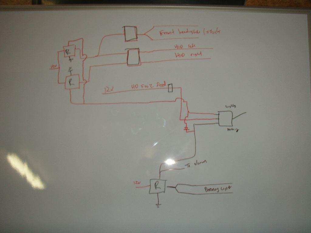
The end result after starting over a half dozen times was the diagram above, which likely means nothing to someone who isn’t actually looking at my wiring. As part of doing this I realized that the wiring I had wasn’t really set up to have a relay powering the parking lights. I need one if I want the alarm to be able to flash them. I’m still not 100% sure how that part gets wired up because the schematic for the fuse panel doesn’t make clear to me how the turn signals work. (Its unclear if I can do this with one relay or if I need two.)
At this point I went out to try to find both connectors that would mesh with the Ron Francis harness as well as a couple of relays with sockets. Unfortunately NAPA, PepBoys and Autozone all didn’t have anything I needed.
That pretty much blew my day. I spent another couple of hours going through DigiKey and Mouser looking for relay options. I discovered at Mouser that the connectors that Ron Francis uses for their harnesses are Delphi 56 Series — and I can order both connectors to hook into the existing harness as well as additional connectors so I can stop using (and potentially replace) the Molex ones I’ve been using. I’m still working on getting an order together but will hopefully place it tomorrow.
So today I decided I wanted to try to make some more progress on the car, but didn’t want to fool with any wiring. I wanted to get the fuel lines buttoned up sooner or later, and figured today would be as good a time as any.
I’ve gone back and forth with the fuel lines for a year — I’m not happy with the hard lines, and debated just getting long -6 and -4 AN braided lines to run from the front to the rear. Its not clear if the state would pass that in an inspection, even though technically its safer. In either case, I figured I could deal with the positioning of the large fuel line and maybe bend the smaller one.
The Powerjection ECU can control fuel pressure on its own — it pulses the ground line going to the fuel pump and basically modulates the power of it. Its unclear if the ECU will work with the in-tank fuel pump I have (I also have an external one, but didn’t use it.) I’m hoping I don’t need the return line, but wanted to run it and just cap it off just-in-case.
The outbound fuel line has been mostly done for a long time, although it wasn’t fitted into the engine bay and was sort of sitting in the middle of the headers. I took it off the car and bent it back as best I could to fit the space in the engine bay. (For anyone reading this who is building a car — do this before the engine goes in. Mine look like crap because I can’t bend them in the car and the best fit bends I can’t snake into place.)
I fit the -6AN fitting on the engine end of the line, and then went back and fit and bent the return fuel line, which gets a -4AN fitting on the end.
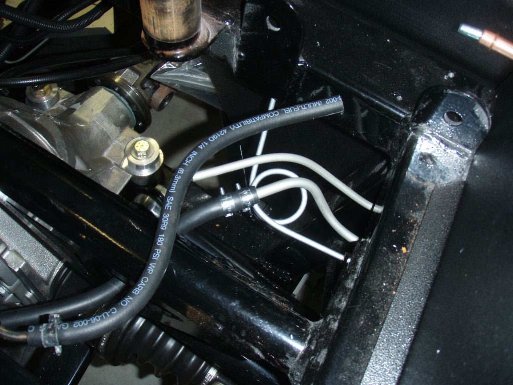
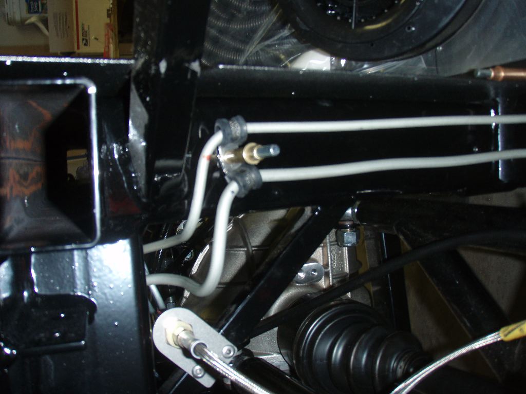
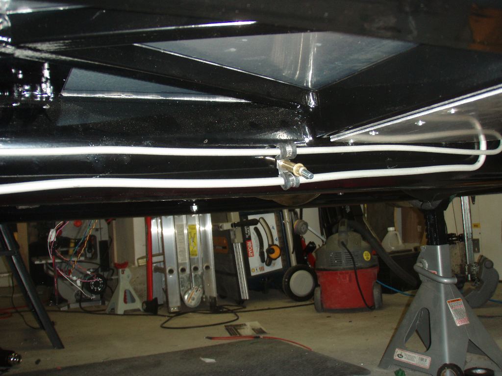
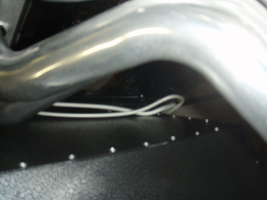
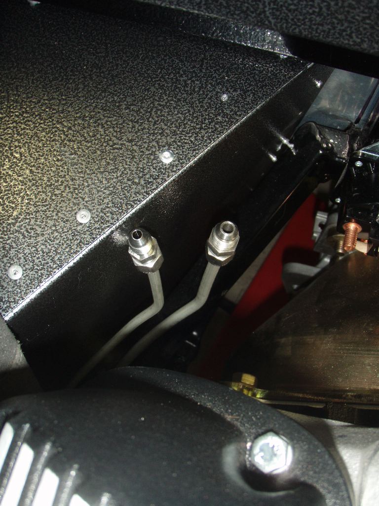
In the photos above, the ines can be seen passing around the car.
The last thing I did was fabricate the -6AN braided hose to go from the hardline to the actual fuel injection system.
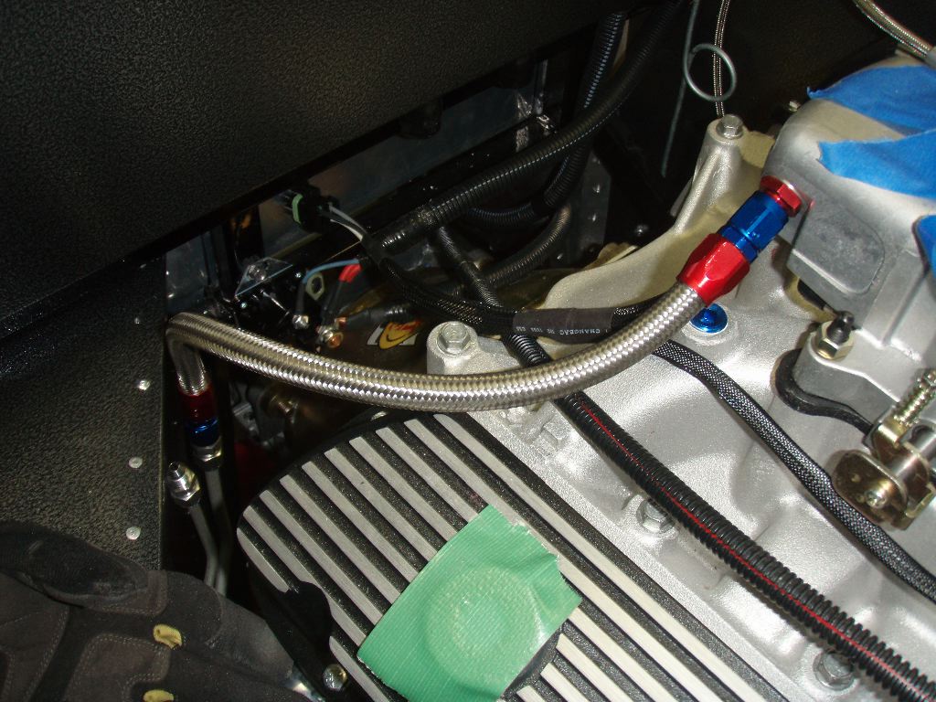
The photo above looks better than it does in person. Mike Forte sold me some hose and a bunch of fittings to make them, but didn’t explain to me how they went together. I found instructions online and frankly, these were a nightmare. You basically trim the hose to length, fit the red collar onto the house and then thread the blue part into the red. The blue fitting squeezes out the house and pinches it into the red collar, holding it tightly. It seems very simple, except I’m not sure the hose Mike sold me actually is the hose you’re supposed to use with these style connectors. It doesn’t look like it based on what I could tell. I got one end on cleanly after 45 minutes of swearing, but the other one bunched up the braided line a bit. I’m not sure if I trust the hose or not under pressure. I may just order an 18″ line online and not have one more thing to worry about. I’ll just toss all the other parts into my “whoops, if I knew then what I do now” pile of discarded parts.