Its Sunday evening, and time for another update. I worked for a half day yesterday and a half day today on various things, but ran into a few issues that really chewed up a lot of my time. I did get a little wiring done, some of the heater plumbing, and a few other little things.
I started off the day on Saturday looking at a few different options of things to work on. I figured I’d get the ignition wiring from the ECU to the coil and distributor done, and maybe take a stab starting to do an alignment on the rear suspension.
While starting to look at the ignition wiring, I realized I may not actually have the combination of parts I thought I had, and in either case I had no idea how the parts I had would get wired together much less to the Powerjection’s ECU. I posted a thread about it on FFCobra, hoping I could get some idea how it all went together.
While waiting for any replies, I decided to take a pass at some more dash wiring.
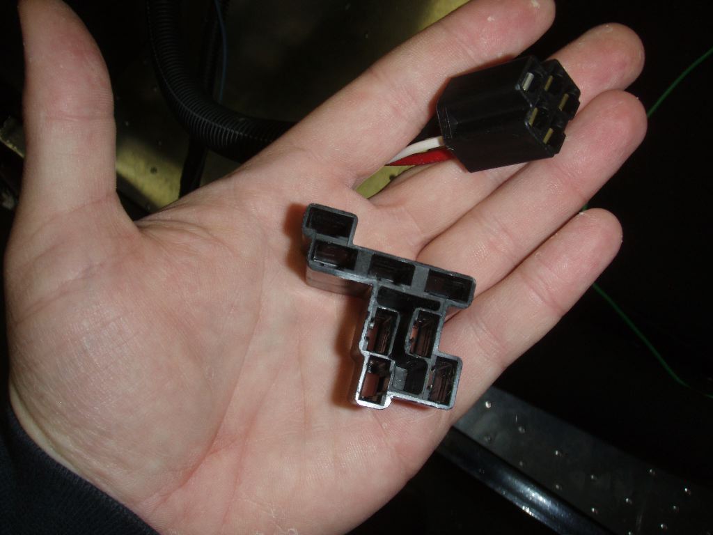
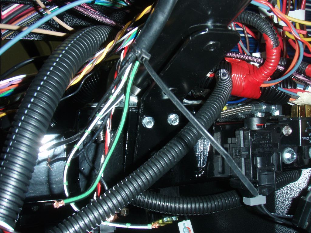
There is still a lot of wiring left. I started off by using a small screwdriver to pop the female connectors out of the unusually-shaped connector intended to work with the headlight switch Factory Five sells (which I don’t have, and in either case I wouldn’t be using even if I did). I used one of the 5-position Delphi connectors I bought a few weeks ago to run them into a connector that I had a matching male version of for the dash. Typically the headlight switch is mounted under the dash on a Factory Five, whereas I have a switch on the dash.
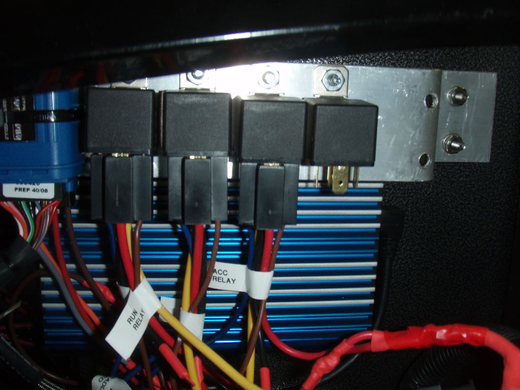
I also mounted one of the Tyco relays I bought at the same time I bought the Delphi connectors — I bought three of them and they are identical to the ones that came with the Digital Guard Dawg system. Technically speaking, any relays would work but its more aesthetic to have matching ones. (Yes, behind the dash — I’d still know they didn’t match…)
This relay is intended to control the parking lights on the car. The normal Ron Francis harness doesn’t use a relay for them (or any other lighting circuit), but I couldn’t wire them to the alarm to flash with the arm or disarm if I didn’t have a relay in the circuit.
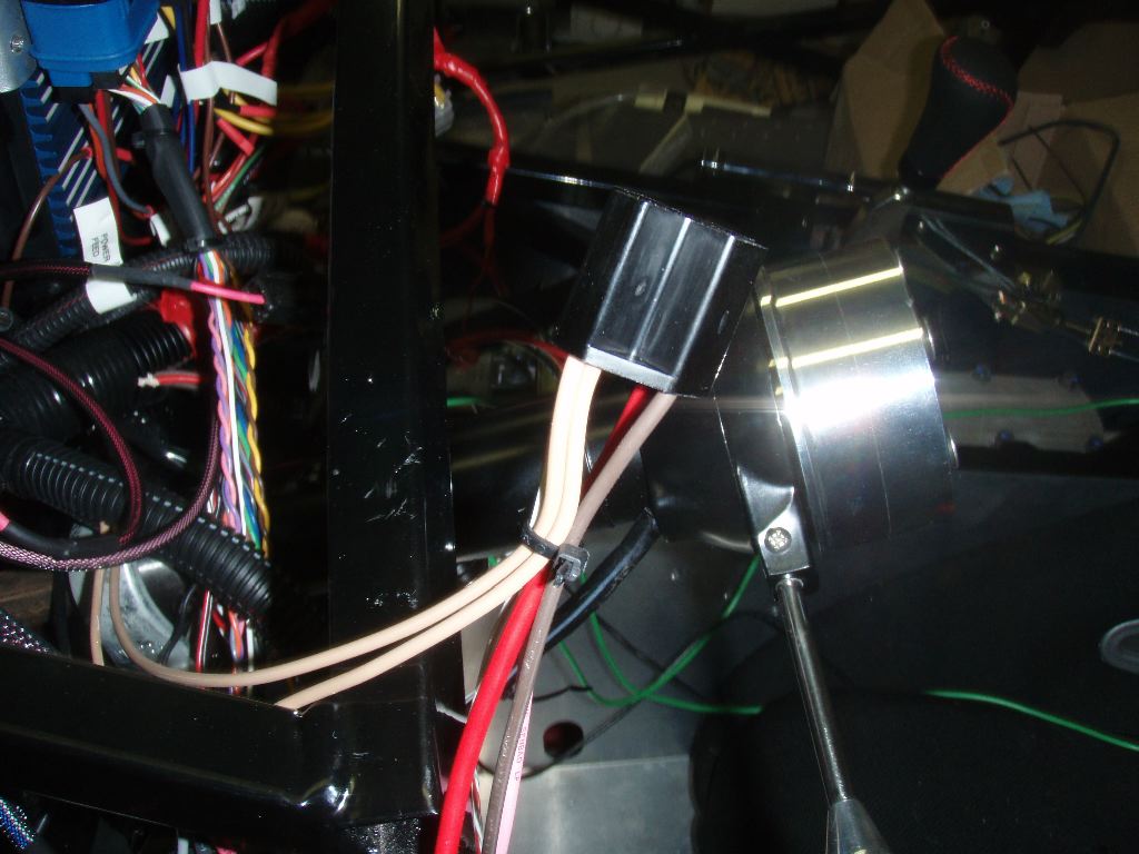
I built the harness for it, as well. The two beige wires are the feeds to the front and rear parking lights. Red is power, brown is ground and the pink and white wires are the trigger from the dash and alarm, respectively. At this point I realized I needed to run the pink line to the dash, so I am going to pull the 5-position connector off the headlight harness and put an 8-position connector on it, so I can use another position for this trigger line as well.
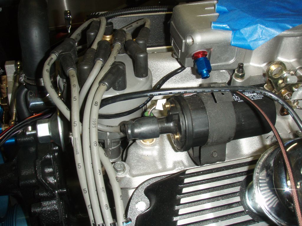
By this point I’d started getting replies related to the coil and distributor. It turned into a long thread over here and it was clear at that point I didn’t nearly have the right stuff and wasn’t going to make any progress. I decided to call it quits for the day and do some more research into it. I’m not entirely sure how I’m going to handle things at this point… the easiest would be to dump the distributor and coil Fortes sold me and get a Ford TFI-compatible distributor and coil, and buy the TFI harness from Powerjection.
While I was up in the dash, I also used three self-tapping screws and mounted the steering wheel turn signal hub to the dash.
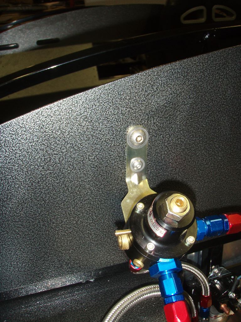
The one final thing I did yesterday was to bolt down the fuel pressure regulator. I went and bought some button capped stainless hardware to match the bolts I used to mount the heater core and ECU on the drivers side of the car. I’m trying to keep all the visible hardware on the firewall consistent that way.
While out buying the hardware for the dash, I also hit NAPA and bought the heater control valve I needed (from a mid-90’s V6 Ford Ranger).
This morning I decided I’d start to hook up the heater plumbing. I realized after poking around that I had a long length of half inch heater hose, which doesn’t make much sense because the fittings are all 5/8″ (and I suspect the outlet on the water pump is actually 3/4″). I had to take a trip back out again to Autozone for some hose and clamps, plus I lit Lowes in an attempt to find a combination of copper fittings that would work better to hook to the heater core than the aluminum outlets that came with it.
I bought about $40 worth of copper plumbing bits to attempt to make a custom-fitted set of outlets for the heater core, but discovered that the fittings on it are not 1/2″ NPT, but something slightly bigger. I’m not sure what they are, so I decided to go ahead and make do with the fittings that came with the heater core.
The aluminum fittings come out the bottom of the firewall. Unfortunately I seem to have misplaced one of the O-rings, so I didn’t Teflon tape and wrench these down. I had both, and I think I dropped it while I was experimenting with different ways of putting stuff together. I hope I can find it, if not I’ll have to try to find a similar one at Lowes this week.
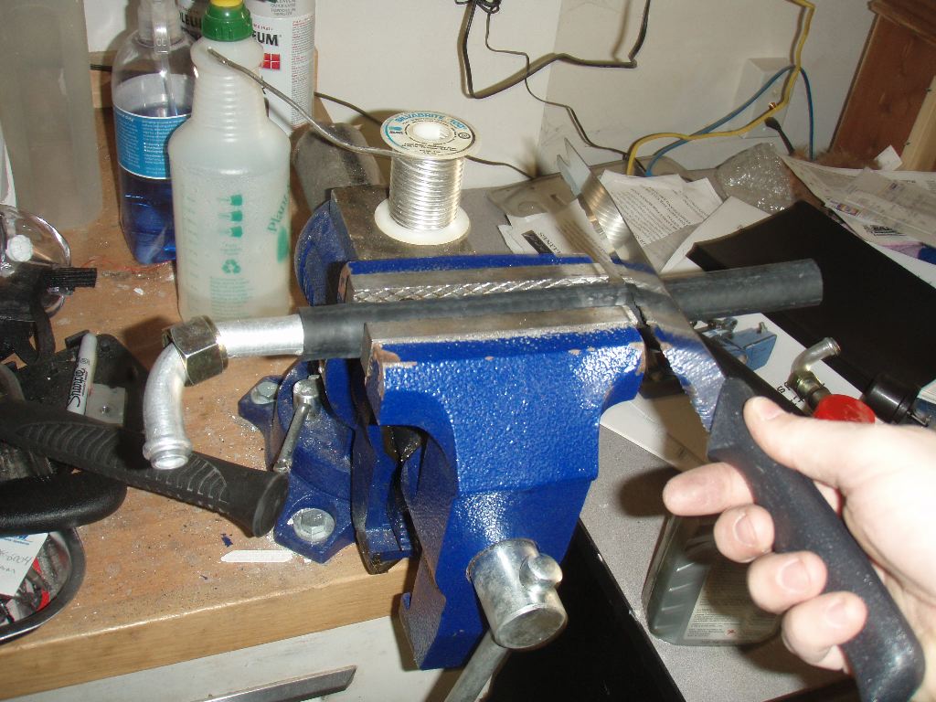
Two short bits of hose were cut to get the staggered outlets aligned together to fit into the heater valve. A Ginsu knife makes for easy hose cutting. Cuts through hose and will continue to cut a tomato like… um… well a knife or something. In either case, it works well.
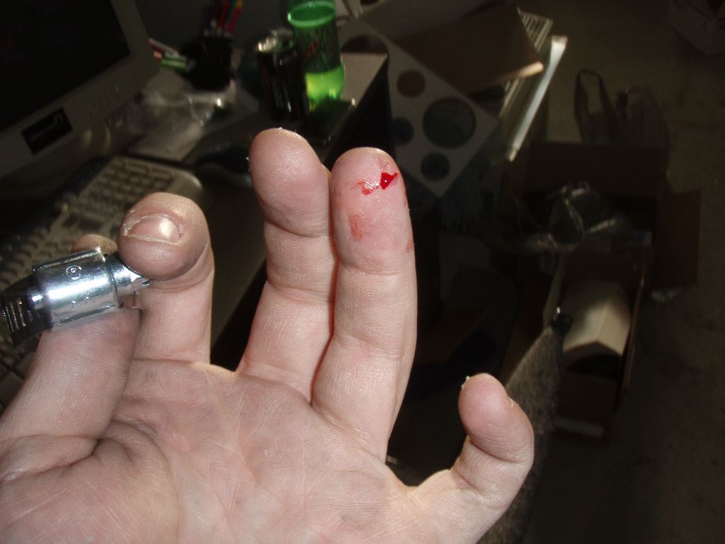
While opening the package of clamps I somehow papercut my finger. How one does that with a piece of cardboard is beyond me, but I managed it. Sacrifice to the car gods, I suppose.
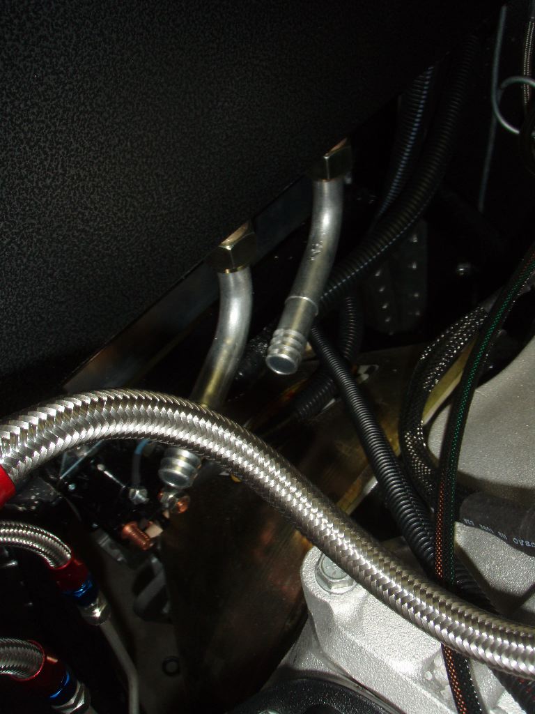
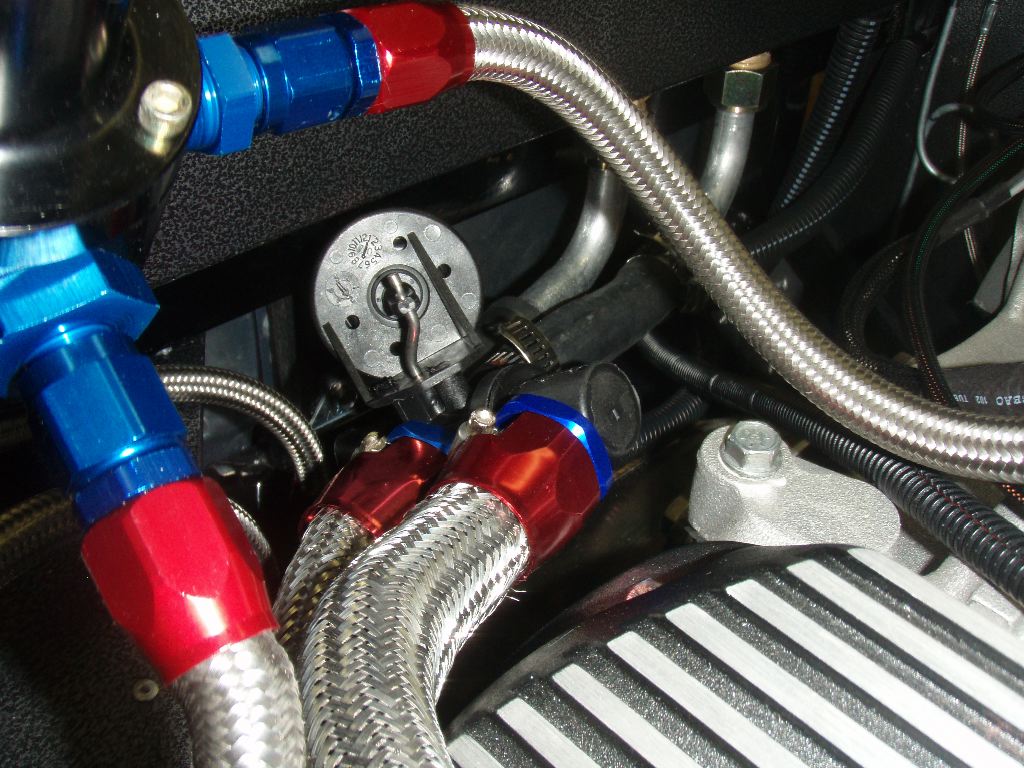
I measured out the two bits of hose going from the engine to the heater control valve and cut and fit them. While at Autozone I bought an engine “dress up” kit which came with face anodized -AN fittings and slip-on braided stainless hose that is meant to go over things like heater and radiator hoses. Considering all my fuel lines are real -AN fittings, I figured it would help the overall look of the engine.
I had a bit of drama trying to get the hose onto the water pump inlet — which is why I suspect its really a 3/4″ fitting, but heating the hose up with some hot water and stretching the rubber a bit with a pair of pliers opened up the end enough to squeeze it on.
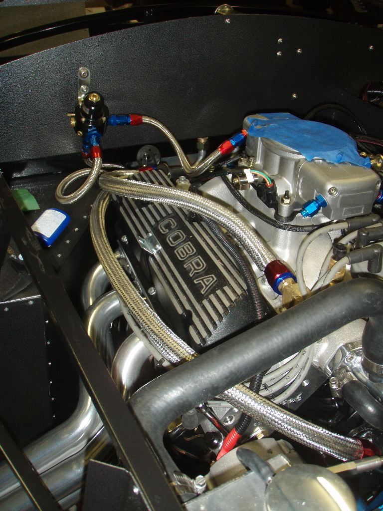
Overall the hoses look pretty good. From up close its obvious that its just something run over the stock hoses, but a glance at the engine bay looks good.
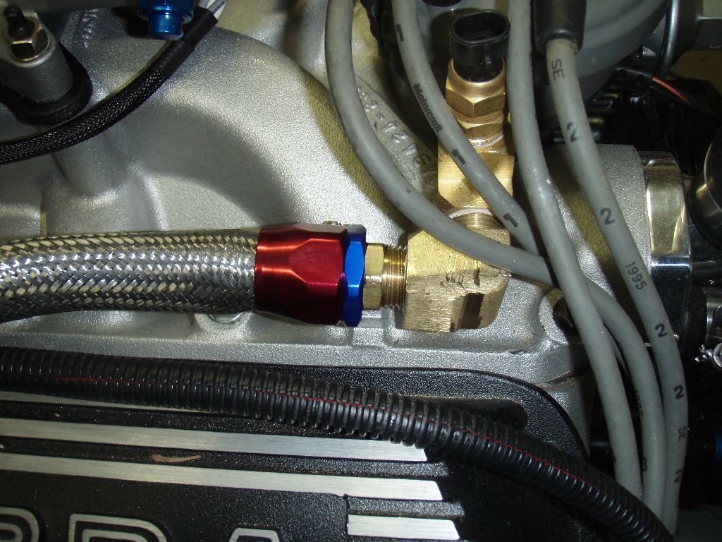
This is the water outlet from the intake.
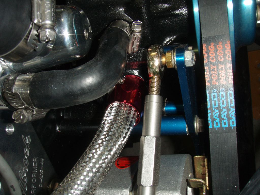
This is the inlet to the water pump. I had to pop the blue trim ring off to be able to fit the 5/8″ end over the 3/4″ inlet, but it looks fine.
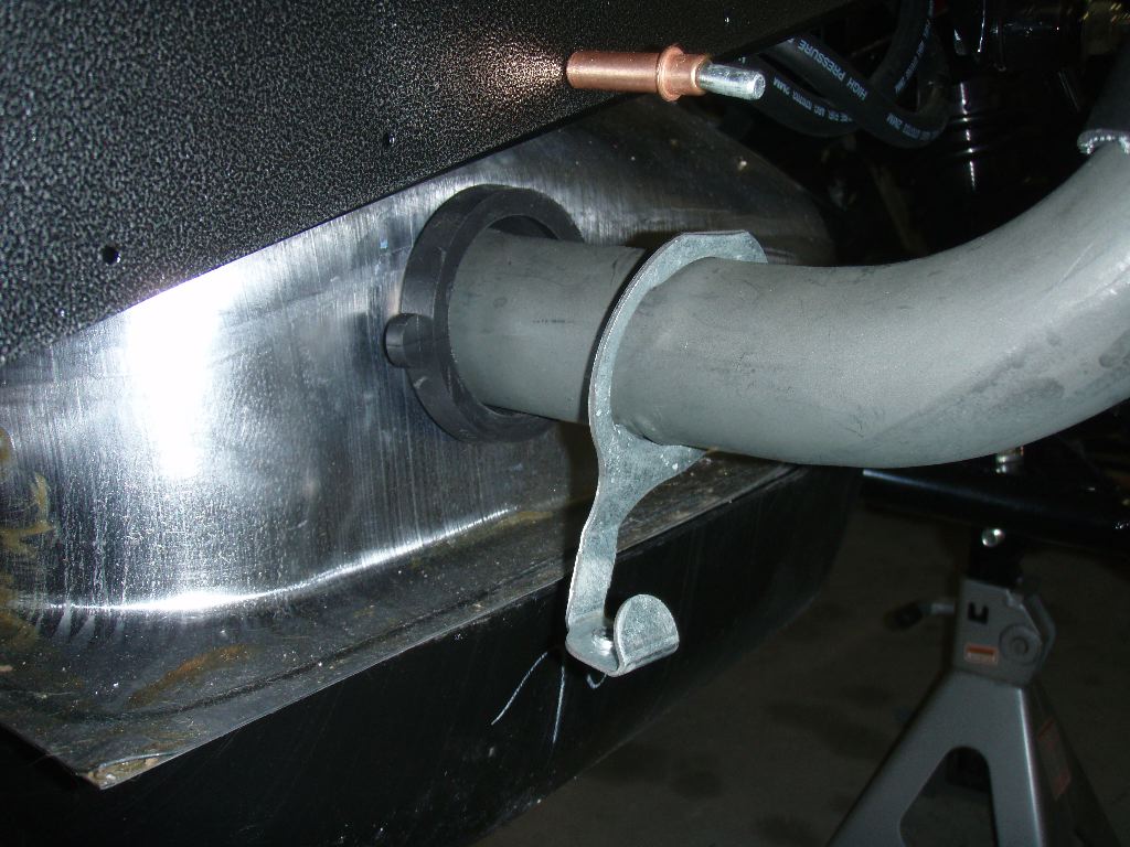
The other two ends are clamped onto the heater control valve, which is then connected to the outlets from the heater core. This is a vacuum controlled valve. At normal pressure, the heater is active, but it can be bypassed by applying vacuum to it. This will let me shut the coolant off going to the heater core during the summer and use the same ducting for cool air.
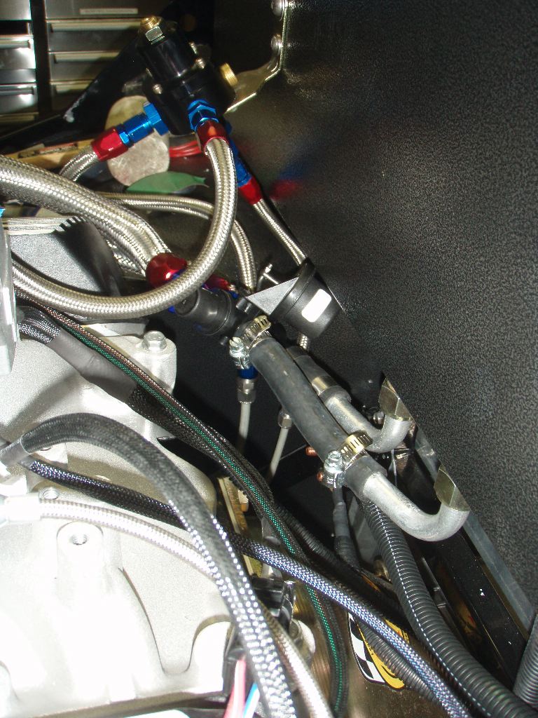
A shot from the drivers side of the car shows the hoses going to the heater core. I’m not 100% sure I’m happwith this — I may put slightly longer hoses on this side, but its okay for now. I have to take the heater core side back apart when I find that damn O-ring anyway.
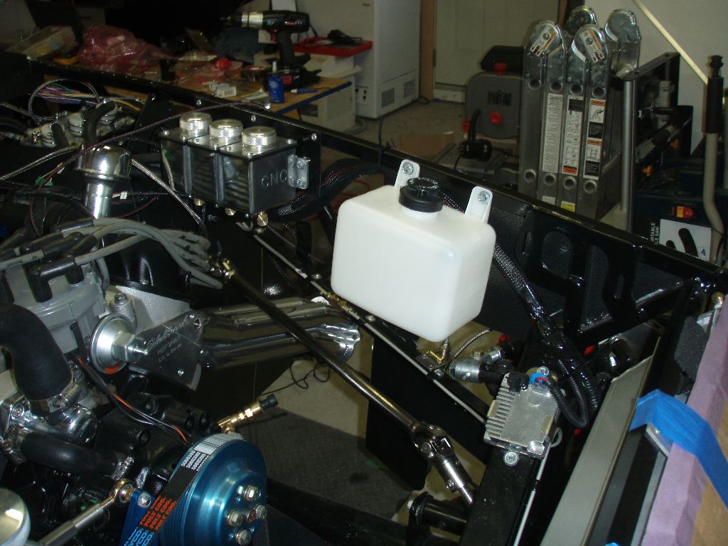
Another thing I did today was screw the recovery tank onto the drivers side of the car. This tank is used to catch overflow coolant from the degas tank and to feed coolant back into the system when it needs more. I’ve experimented with a bunch of places to have it on the passenger side (where the degas tank is), and had looked at mounting it onto the X-member in front of the engine, but I realized that it would work best if it was at the same level as the degas tank. There’s a few feet of hose running along the X-member, but its sealed so I think the system will have no problems both pushing coolant into the tank and drawing it back into the cooling system.
I also spent a bit of time today getting the fuel filler put together. Unfortunately I can’t find the clamps for it, but I did get the stock filler cut and positioned in the fuel tank. This lead to even more confusion, and I had another good thread going on FFCobra here about it.
There’s something very… hacky… about the way this all goes together. Although Fortes sold me the filler, the tank and the clip in the photo above, they don’t actually go together. Typically I guess, from what I learned in that thread, the filler goes in the tank and then is clipped in using the metal clip by bolting it to a hole in the edge of the tank. My tank doesn’t have a hole, nor can I just drill one because the welded seam on the tank is at the very edge of it. I’m not sure why Fortes sold me the damn clip then. In either case, I’ll probably fabricate something to help support it. More pics of that in the future when I get that figured out.
In all, I got a lot of little things done, but not as much as I hoped. I still think I can start the engine in a few weeks, assuming I can figure out a solution to the distributor and coil issues.